1 Flashback: the wing-cars era
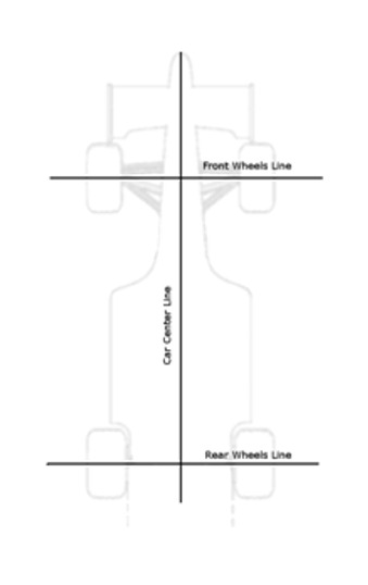
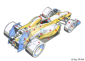
The design of parts visible from under an F1 car is defined by strict rules aimed at reducing the well known "ground effect", in order to reduce performances for safety reasons.The "ground effect" is due to the interaction between a wing-shaped surface moving close to the ground (approx 100 mm or less for an F1 car) and the ground itself. As a result, impressive values of downforce can be obtained. The effect is maximized if impeding the passage of airflow from car sides to the underside, that is, if a tunnel can be formed by the car underside (wing-shaped), the ground and seals below later panels. This was obtained starting 1976 (Lotus 77 model) by applying lateral plastic brushes, later evolved into metal "mini-skirts" (1977, Lotus 78 model) and sliding skirts into side panels (1978, Lotus 79 model). F1 cars based on these designs, adopted by all teams since 1979, were commonly referred to as "wing cars".As possible skirts' failure, causing immediate dramatic reduction of downforce, resulted into risk of severe accidents, FIA regulations progressively introduced rules that control the design of the underside of F1 cars in order to minimize the ground effect.2 Season 2005: design rules for the underside2.1 IntroductionBasically we can think about two concepts inspiring these rules: defining a fixed design for the underside (to avoid wing-shaped profiles) and requiring a panel (skid-block) to be applied under the car (to grant a minimum distance from the ground when the car is running and comformity tests can't be easily performed).Before seeing details let's start with some definitions first (see pic. 1).
 |
pic. 1
|
Front Wheels line: a line that passes through the center of front wheels
Rear wheels line: a line that passes through the center of rear wheels
Car center line: a longitudinal line that passes through the center of the car
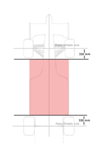
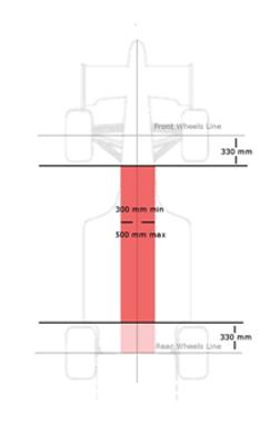
2.2 Surfaces facing the groundWe'll address here the area extending from 330 mm behind the Front Wheels Line e 330 mm forward the Rear Wheels Line (see pic. 2).
 |
pic. 2
|
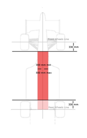
In this area, parts facing the ground must be placed only on two planes (flat surfaces): the reference plane and the step plane. These planes must be parallel.The reference plane (see pic 3) is the lowest part of the car bodywork, it must be symmetrical about the Car Center Line, and have a 300 mm min width and 500 mm max width. Additionally, the reference plane must extend from 330 mm behind Front Wheels Line to the Rear Wheels Line.Note that the reference plane's surface doesn't need to be a rectangle, as shown in the drawing: it can have any shape as long as it be symmetrical about the Car Center Line.
 |
pic. 3
|
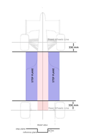
Remaining parts must be on the step plane (see pic 4), up to a max width of 1400 mm. Step plane must be placed 50 mm above the reference plane. Again, the surfaces on the step plane don't have to be rectangular: they simply follow the shape of the reference plane, which is free (but symmetrical).
 |
pic. 4
|
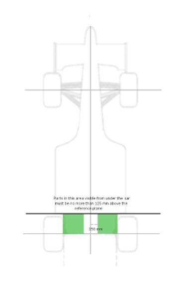
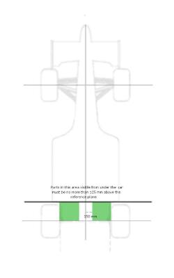
Parts visible from under the car that are more than 150 mm from Car Center Line and are behind a point 330 mm forward the Rear Wheels Line up to the Rear Wheels Line may not be more than 125 mm above the reference (see pic 5).
 |
pic. 5
|
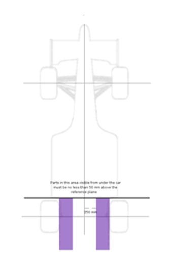
Parts visible from under the car that are more than 250 mm from Car Center Line and lie behind a point 330 mm forward the Rear Wheels Line may not be less than 50 mm above the reference (see pic 6).
 |
pic. 6
|
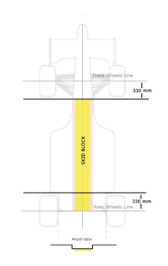
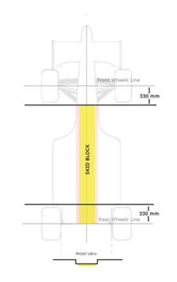
2.3 The skid-blockParts placed on the reference plane must be fitted with a rectangular skid-block, with a width of 300 mm and thickness of 10 mm (see pic7). The skid-block must extend from 330 mm behind the Front Wheels Line to the Rear Wheels Line.This panel provides a way to grant a minimal distance from the ground even when the car is running, that is, in the period of time when technical verifications are not possible. The concept here is that possible friction between the ground and the skid-block would decrease the panel thickness. Panel's thickness is verified when the car stops running.
 |
pic. 7
|
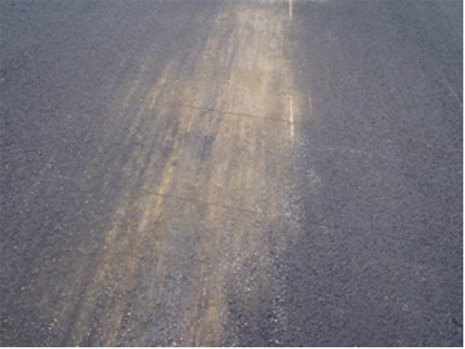
The material used to make the skid-block must have a gravity between 1.30 and 1.45. The skid-block must have seven holes, with specified diameter (50 mm and 80 mm), place at defined positions. These holes are used to verify thickness comformity after the race. A thickness tollerance of +/- 1 mm is allowed after the race.Pic 8 shows the effect of skid-blocks occasionally impacting the ground (Monaco GP).
 |
pic. 8
|
Copyright © - www.audiolabs.it |